
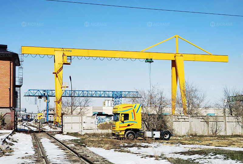
Cantilever gantry cranes are widely used in industrial yards, railway terminals, construction sites, and heavy manufacturing zones where overhanging load access, extended reach, and optimized workspace are essential. Specifically, the 20-ton cantilever gantry crane offers a flexible balance between load capacity and structural efficiency. But with the added reach of the cantilever arm comes added complexity in terms of structural balance and stability.
This article examines the structural design principles, balance mechanisms, and stability factors that ensure the safe and efficient operation of a cantilever 20 ton gantry crane, including its components, engineering design, and practical considerations.
1. Understanding the Cantilever Gantry Crane
A cantilever gantry crane is distinguished by one or both ends of the crane’s girder extending beyond the supporting legs. This structural overhang enables the crane to handle loads outside the span of the main support legs – ideal for transferring loads from truck beds, railcars, or onto platforms beside the track.
A 20-ton cantilever gantry crane typically includes:
-
Box-type or truss-type girders with cantilever extensions
-
Rigid or flexible supporting legs
-
Travel mechanism (rails or rubber tyres)
-
Trolley and hoist system
-
Wind-resistant and anti-sway design elements
Its balance and stability rely heavily on precision engineering, material strength, and dynamic load control.
2. Structural Balance: Definition and Importance
Structural balance refers to the equilibrium state where all applied loads, including the crane’s self-weight, lifted loads, and environmental forces, are evenly distributed and counteracted by the structure without excessive deflection or deformation.
In cantilever cranes, imbalance is inherently present due to the overhanging section. To maintain structural balance:
-
The cantilever load must be offset by counterbalancing forces within the girder and supporting legs.
-
The center of gravity (CG) of the crane must stay within the support base area, even during lifting operations.
-
Structural deformation, such as girder bending or torsion, must be within allowable limits.
Failure to maintain balance may lead to:
-
Girder instability or failure
-
Excessive deflection or sway
-
Uneven wheel load distribution
-
Reduced crane lifespan and safety hazards
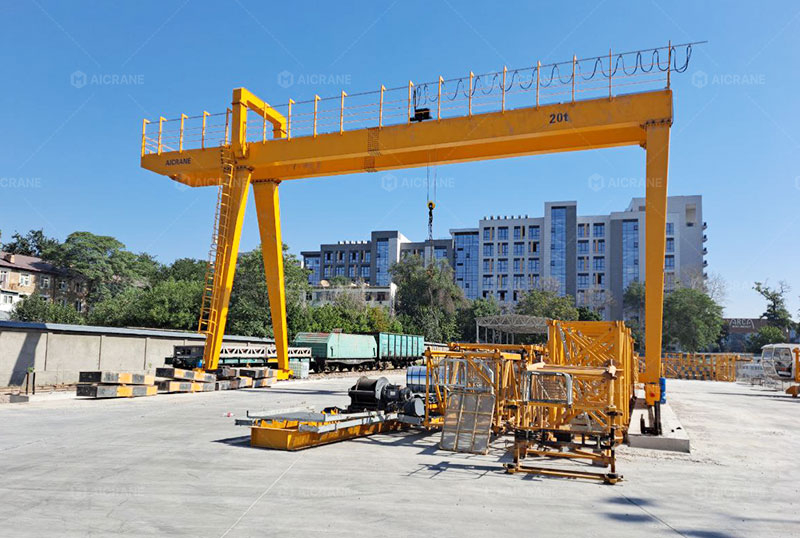
3. Key Structural Elements That Maintain Balance
a. Main Girder Design
For a 20-ton cantilever gantry crane for sale, the main girder is usually a box-type welded steel beam, designed to:
-
Withstand bending moments created by the overhang
-
Handle torsional stress induced by lateral loading
-
Distribute live and dead loads to the support legs efficiently
The cantilever section is integrated or bolted onto the main girder and designed with a gradual taper or reinforced flange plates to manage the stress transition smoothly.
b. Support Legs and Base
Typically, the crane has:
-
One rigid leg: fixed to the girder with a rigid connection, controlling lateral movement.
-
One flexible leg: connected using a hinge or sliding joint to accommodate girder deflection.
The legs are mounted on wheels or rails, and their base must be wide enough to maintain the crane’s balance. In outdoor installations, the track gauge may range from 10 to 30 meters, depending on the cantilever length and load handling needs.
4. Load Distribution and Wheel Load Calculations
Proper wheel load distribution is a critical aspect of structural balance in cantilever gantry cranes. The 20-ton rated load and the overhang produce asymmetric loading, which must be analyzed during design.
Designers consider:
-
Live load impact factors
-
Dynamic amplification due to acceleration and braking
-
Load eccentricity when the hoist is on the cantilever arm
-
Wind and seismic loads
Software tools like finite element analysis (FEA) are used to model these effects and verify that each wheel or bogie assembly is loaded within safe limits. Reinforcement may be added to the cantilever side to avoid overloading one track or tyre line.
5. Structural Stability Factors
a. Wind Load Resistance
Wind is a major external destabilizing force for cantilever cranes, especially those operating outdoors. Structural stability is achieved through:
-
Low center of gravity design
-
Wind-resistant bracing between legs and girder
-
Travel locking devices or rail clamps that anchor the crane during idle periods
For safety, cranes are usually designed to withstand wind speeds up to 25 m/s (operational) and 50 m/s (out of service), depending on location and local building codes.
b. Anti-Sway Mechanisms
Structural sway due to load movement or braking can compromise stability. Advanced cantilever gantry cranes incorporate:
-
Anti-sway control systems
-
Variable frequency drives (VFDs) for smooth acceleration
-
Mechanical buffers and damping systems
The structural design includes torsion-resistant girders and cross bracing to minimize lateral sway.
6. Foundation and Track Considerations
The foundation plays a vital role in overall crane stability. For rail mounted gantry cranes:
-
The rail alignment must be precise and level to prevent twisting of the structure.
-
Track bed foundations are designed to support not only the wheel loads but also horizontal and vertical forces from wind, skewing, and braking.
The crane manufacturer typically provides wheel load charts and reaction force diagrams for civil engineers to design the proper foundation and anchorage.
7. Seismic and Emergency Stability
In earthquake-prone regions, cantilever gantry cranes must also incorporate:
-
Seismic restraints and locking systems
-
Flexible joints to absorb ground motion
-
Emergency stop systems that automatically secure crane movement
Seismic stability is verified through analysis using Eurocode 8, GB50011, or similar seismic design standards.
8. Maintenance and Structural Health Monitoring
Structural balance and stability are not only design considerations – they require ongoing monitoring:
-
Routine inspection of the girder for deflection, fatigue, and weld cracks
-
Checking wheel alignment, track wear, and cantilever bolt tension
-
Using structural health monitoring systems (SHMS) with sensors to track load impact and structural response in real-time
This proactive approach ensures long-term reliability and reduces the risk of failure under load.
Conclusion
Maintaining structural balance and stability in a 20-ton cantilever gantry crane is a multidimensional challenge. It involves meticulous engineering of the girder, cantilever arm, legs, base, and load distribution systems. Additionally, environmental factors like wind and seismic activity must be accounted for during design and operation.
As demands for higher lifting efficiency and yard flexibility increase, cantilever cranes remain a smart solution – but only if proper structural stability is ensured. Whether through reinforced steel design, anti-sway technology, or precision foundation engineering, the stability of cantilever gantry cranes is the foundation of their performance and safety.